Description
Single row cylindrical roller bearings are well suited to carry high radial forces. Depending on the design or the placement of shoulders, cylindrical roller bearings are capable of withstanding low axial forces in one or both directions. Single row cylindrical roller bearings are detachable bearings – making it easier to assemble or disassemble the bearing, primarily for service purposes.
Dimensions/standards
In single row cylindrical roller bearings, the main dimensions are standardized according to ISO 15 (Radial bearings – boundary dimensions), DIN 616 (Roller bearings – boundary dimensions) or DIN 5412-1 (Roller bearings – Single row cylindrical roller bearings).
The abutment ring (HJ) dimensions are standardized according to DIN 5412-1 and ISO 246 (Cylindrical roller bearings – abutment rings).
Tolerances
As the default, we produce single row cylindrical roller bearings at SLF with standard tolerances (PN) according to DIN 620-2 (Roller bearing tolerances – tolerances for radial bearings) and ISO 492 (Radial bearings – dimensions and tolerances). We also deliver bearings with P6, P5 and P4 tolerances upon request.
Bearing design types
SLF manufactures cylindrical roller bearings in the design types NU.., NJ.., NUP.. and N. The cylindrical roller bearings and bearing components, such as abutment rings (HJ), can also be delivered as special design types RNU, NUB, NJP, NU+HJ, NJ+HJ, as well as individual inner rings (L..) with – if appropriate – appertaining shoulder rings LNJ, LNU, LNJP and LNUP.
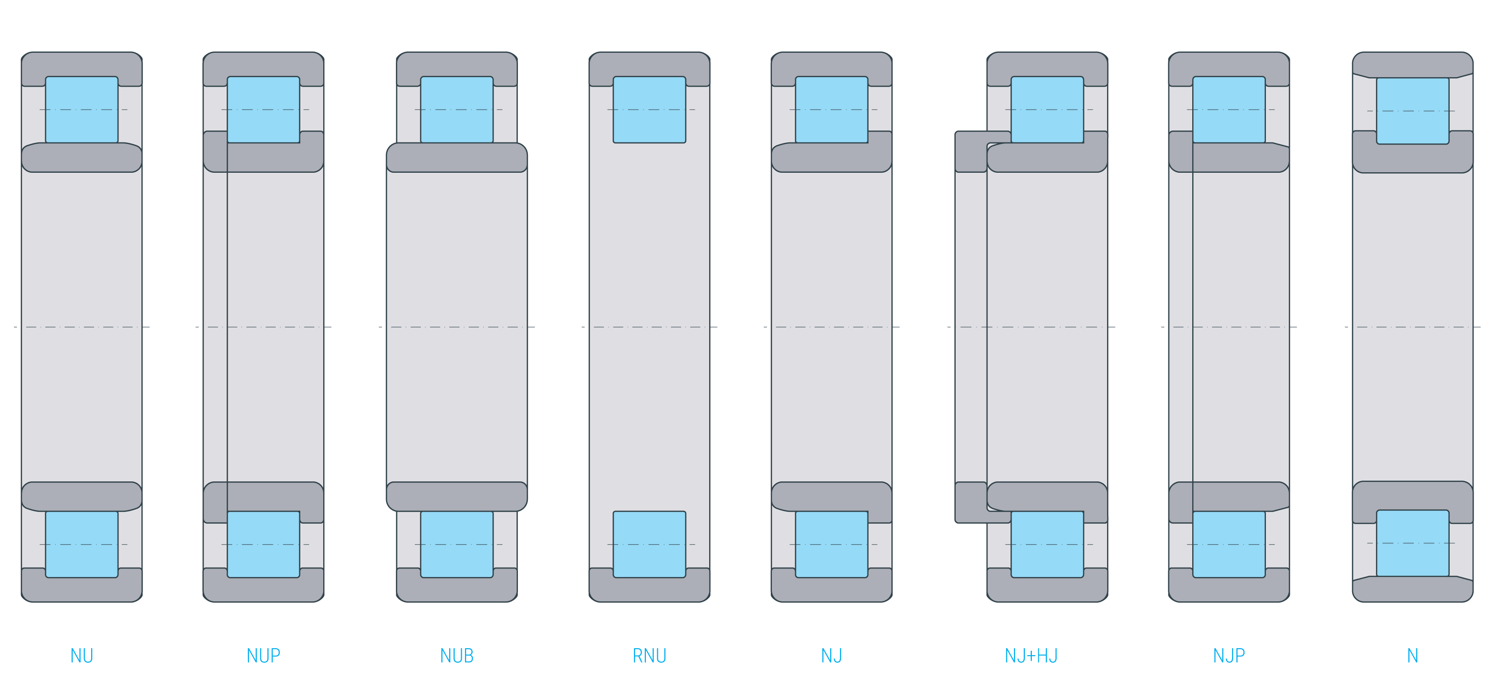
The NU design is composed of an outer ring with two shoulders and an inner ring with no shoulder. Although bearings of the NU type are not capable of carrying axial forces, they provide length compensation inside the bearing, and are, in principle, floating bearings. The bearings can be detached. For use as step bearings, they can be connected by abutment ring HJ.
In the N design, the inner ring has two shoulders while the outer ring has none. N design bearings cannot carry axial forces. However, they provide for length compensation inside the bearing and are, in principle, floating bearings. The bearings can be detached.
The NJ design is composed of an outer ring with two shoulders and an inner ring with one shoulder. As a result of this design, the bearing can carry axial forces in one direction. It is possible to combine NJ supporting bearings with an HJ abutment ring to obtain a fixed bearing.
The NUP design is composed of an outer ring with two shoulders, an inner ring with a fixed shoulder, and a loose rib. The bearings are used as fixed bearings to carry alternating axial forces.
We produce single row cylindrical roller bearings in the 10, 2.E, 22..E, 3..E, 23.E and 4 series.
To prevent damage from electrical current, SLF also manufactures current-insulating cylindrical roller bearings (designation suffix J20A, J20A1, J20B), which insulate against current up to 1000 V.
We also produce the SLF cylindrical roller bearings as LONGLIFE products upon request. LONGLIFE bearings have a higher fatigue limit than the standard bearing. Both bearing and packaging are marked as LONGLIFE.
Clearance
All cylindrical roller bearings made by SLF are standard delivered in the clearance class CN according to DIN 620-4 (Roller bearing tolerances – radial clearance) and ISO 5753-1 (Roller bearings – clearance – radial clearance). We can deliver design types in other bearing clearance classes or with special clearances upon request.
The components of bearings of the type made by SLF according to DIN 5412-1 with the same clearance are interchangeable. Bearings with indicated radial clearance are not interchangeable as a rule.
Clearance table for cylindrical roller bearings:
Cage
In standard design, SLF cylindrical roller bearings are composed of a cage made of glass fiber-reinforced polyamide 66 (designation suffix TVP2). Bearings with this cage type are suitable for higher temperatures up to 120 ° C over the long term. If lubricated with oil, the additives in the oil can reduce the cage’s operational life. As an alternative, we supply the bearings with brass cage (M1, M1A), riveted on the web plate. We can also deliver sheet plate cages (J) upon request.
Working temperature
SLF single row cylindrical roller bearings with a maximum 120 mm outer diameter are standard stabilized in dimensions by S0, meaning that they are subjected to heat treatment that makes them usable up to 150 °C. Above a 120 mm outer diameter, the cylindrical roller bearings are standard stabilized in dimensions by S1, meaning that they are heat treated to make them usable up to a working temperature of 200 °C. However, as a rule, the maximum working temperature is not limited by the dimensional stability of the bearing rings and rollers. In many cases, it is limited by the cage or the lubricant. Please find the necessary information in the relevant chapters. If you are uncertain or have specific questions regarding our bearings’ temperature limits, don’t hesitate to contact the SLF team.
Greasing/lubrication & sealing
We manufacture single row cylindrical roller bearings without seals. Consequently, the bearing location must be sealed around/ on the surrounding components. The sealing must ensure that no moisture and/ or contaminants can enter the bearing and that no lubricant is lost.
Single row cylindrical roller bearings are delivered ungreased but must be lubricated with oil or grease. Choose the lubricant according to the application.
Dimensioning
Dynamic equivalent load
For floating bearings, the following equation can be applied:
For step and fixed bearings, there may exist an axial force Fa in addition to the radial force Fr. The ratio of load must be considered.
| $$P = F_r$$ | for | $$\frac{F_a}{F_r} \leq{e}$$ |
| $$P = 0,92 * F_r + Y * F_a$$ | for | $$\frac{F_a}{F_r} > e$$ |
| P | dynamic equivalent load [kN] |
| Fr | radial dynamic load [kN] |
| Fa | axial dynamic load [kN] |
| e, Y | factors [-] |
Factors e and Y for single row cylindrical roller bearings
| Series | Mathematic factors | |
|---|---|---|
| e | Y | |
| NJ2, NUP2, NJ3, NUP3, NJ4 | 0,2 | 0,6 |
| NJ22, NUP22, NJ23, NUP23 | 0,3 | 0,4 |
Static equivalent load
| P0 | static equivalent load [kN] |
| F0r | maximum radial static load [kN] |
Static load safety factor
If cylindrical roller bearings are subjected to static loads, as a rule, inspect static load safety factor S0 in addition to nominal lifetime L (L10h).
| S0 | static load safety factor [-] |
| C0 | static load rating [kN] |
| P0 | static load rating [kN] |
static load rating
To avoid slippage between elements in contact, the cylindrical roller bearings must be sufficiently loaded. A minimal radial load in the order of magnitude
has been shown to be necessary.
In most cases, the radial load resulting from the weight of the components run on bearings combined with the external forces is higher alone than the minimal load required. Should this value not be met, contact an SLF application technician.