Description
Single row angular contact ball bearings have raceways that are offset in the bearing axis direction in the inner and outer ring and carry axial forces in only one direction. In case of a radial load, an axial force emerges in the bearing, and this force must be compensated by a counterforce. Angular contact ball bearings are not used as single bearings, because they carry emerging forces together. Consequently, these bearings are always arranged in pairs or as a bearing set based on mutual matching.
Dimensions/standards
In single row angular contact ball bearings, the main dimensions are standardized according to ISO 15 (Radial bearings – boundary dimensions, DIN 616 (Roller bearings – boundary dimensions) or DIN 628-1 (Radial-angular contact ball bearings).
Tolerances
As the default, we manufacture single row angular contact ball bearings with standard tolerances (PN) according to DIN 620-2 (Roller bearing tolerances – tolerances for radial bearings) and ISO 492 (Radial bearings – dimensions and tolerances). Different tolerance classes or special tolerances can also be delivered upon request.
Bearing design types
The SLF standard portfolio comprises the 718, 719, 70, 72 and 73 series. Other series are manufactured upon request. In angular contact ball bearings with designation suffix B, the contact angle α is 40°, and in bearings without suffix, it is 20° or 30° depending on the series. Here, α is understood as the angle encompassed by the connecting line of the two points of contact between ball and raceways with the radial plane, and under which the load is transferred from one raceway to the other.
All-purpose bearings
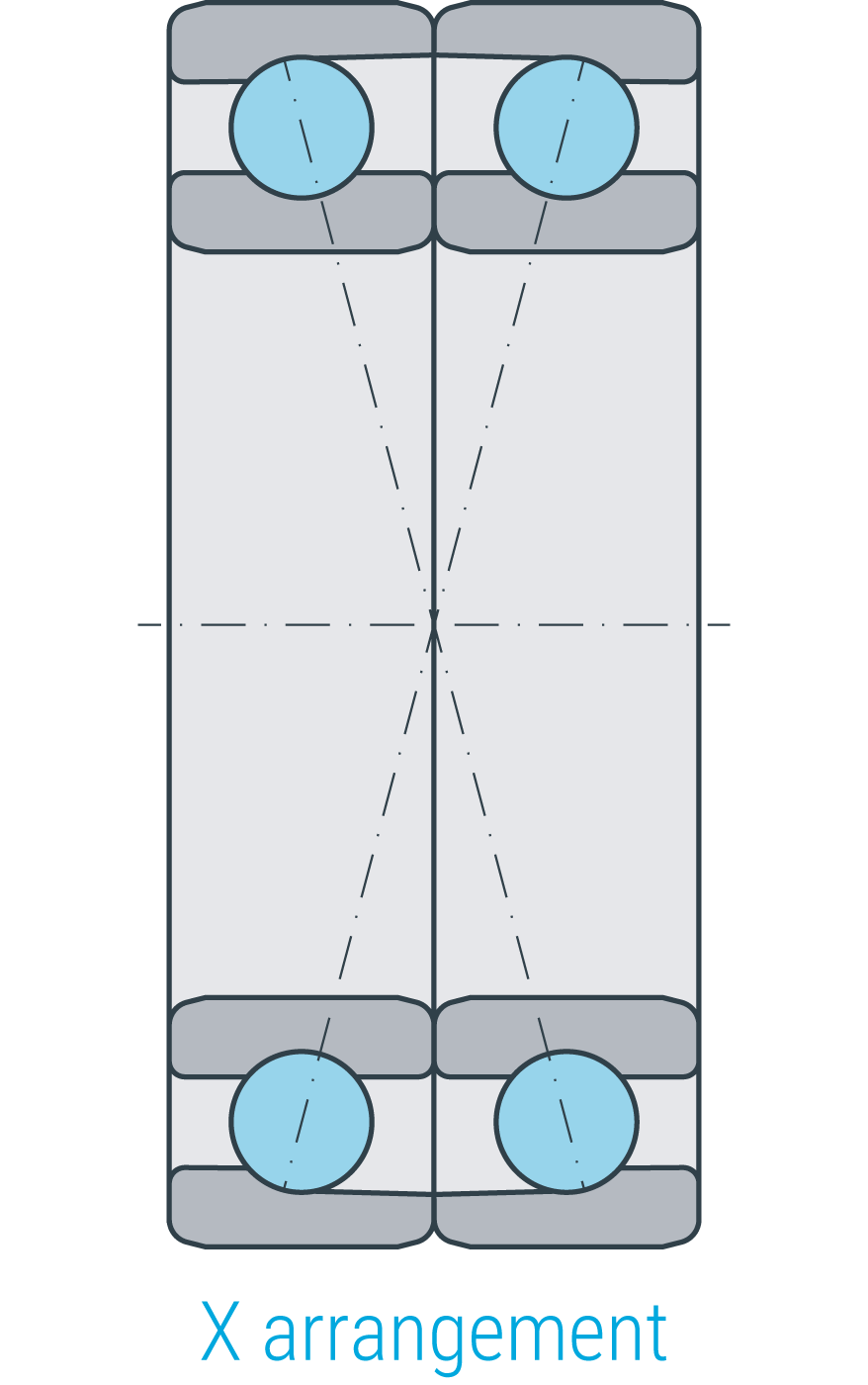
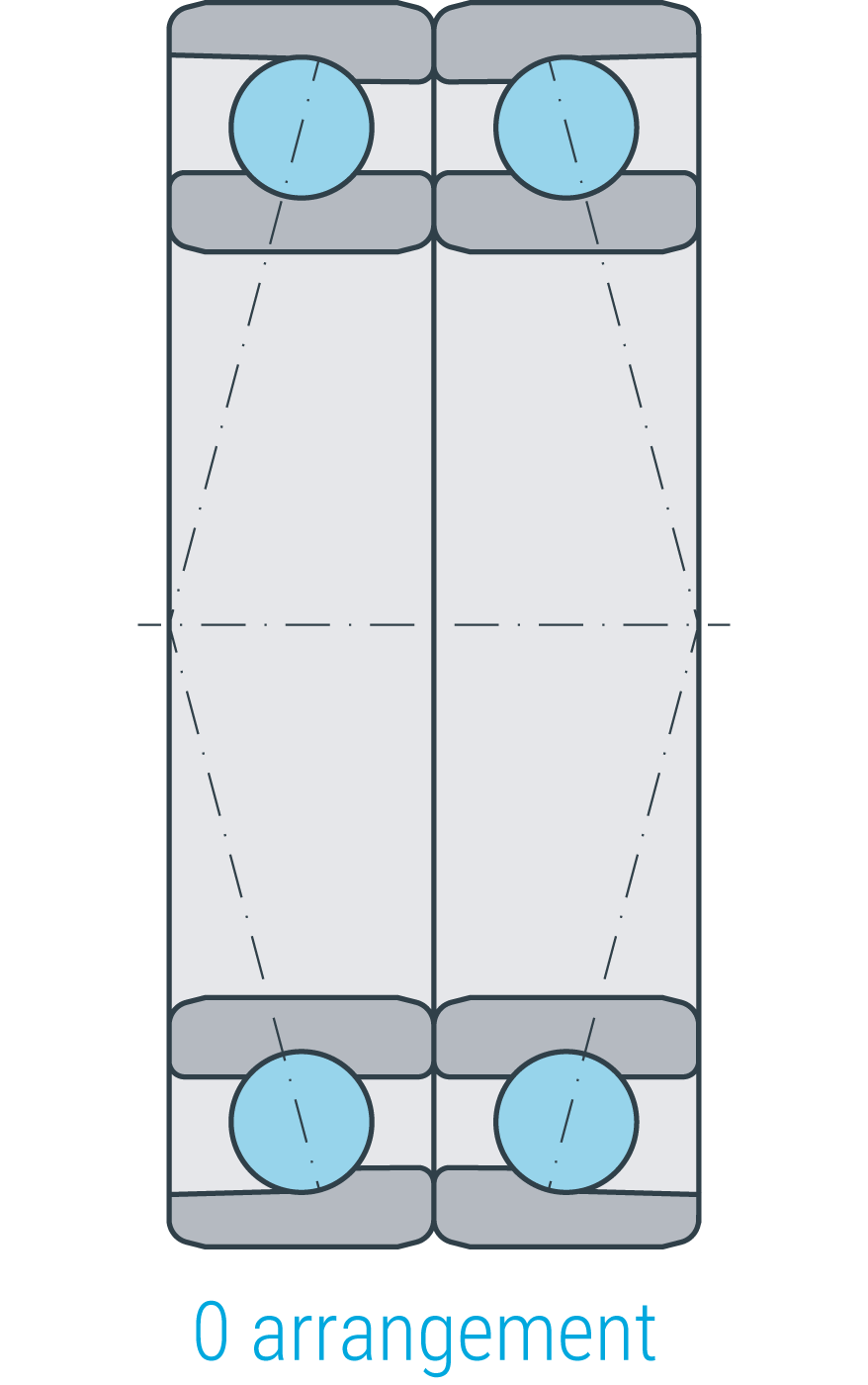
Single row angular contact ball bearings with universal design are intended for installation in pairs in X, O or tandem arrangement. In universal design, the raceways and lateral faces of the bearing’s inner and outer rings are matched so that arbitrary bearings of the same size and preload /clearance can immediately be mounted in the corresponding arrangements. We distinguish the following universal design types:
Universal design
| UA | with axial clearance |
| UO | without clearance (without preload) |
| UL | low preload |
| UM | medium preload |
| US | high preload |
Spacers
For angular contact ball bearings with universal design, it is possible to use spacers for all arrangements. When manufacturing the spacers, ensure that the inner and outer ring have exactly the equal width and are parallel-sided. When desired by the customer, angular contact ball bearings can also be delivered as bearing pairs with spacers, ready to install, in tandem, O or X arrangement.
Other design types
Angular contact ball bearings can also be delivered with ceramic balls or ceramic coating to insulate against electric current passage up to 1000 V. SLF’s angular contact ball bearings are also delivered as ”LONGLIFE“ bearings upon request. Bearings of this design type have a higher fatigue limit than the standard bearing. Both bearing and packaging are marked “LONGLIFE“.
Bearing arrangement
To configure the following bearing arrangements, only bearings with universal design in the identical preload and tolerance class are permitted.
O and X arrangements are applied to carry axial loads in both directions or to carry high radial loads.
In the O arrangement, the large faces of the outer rings are adjacent, whereas, in the X arrangement, the small-sized faces of the outer rings are adjacent.
The O arrangement is a very stiff mounting, has greater support distance H than the X arrangement, and, as a result, higher tilting resistance.

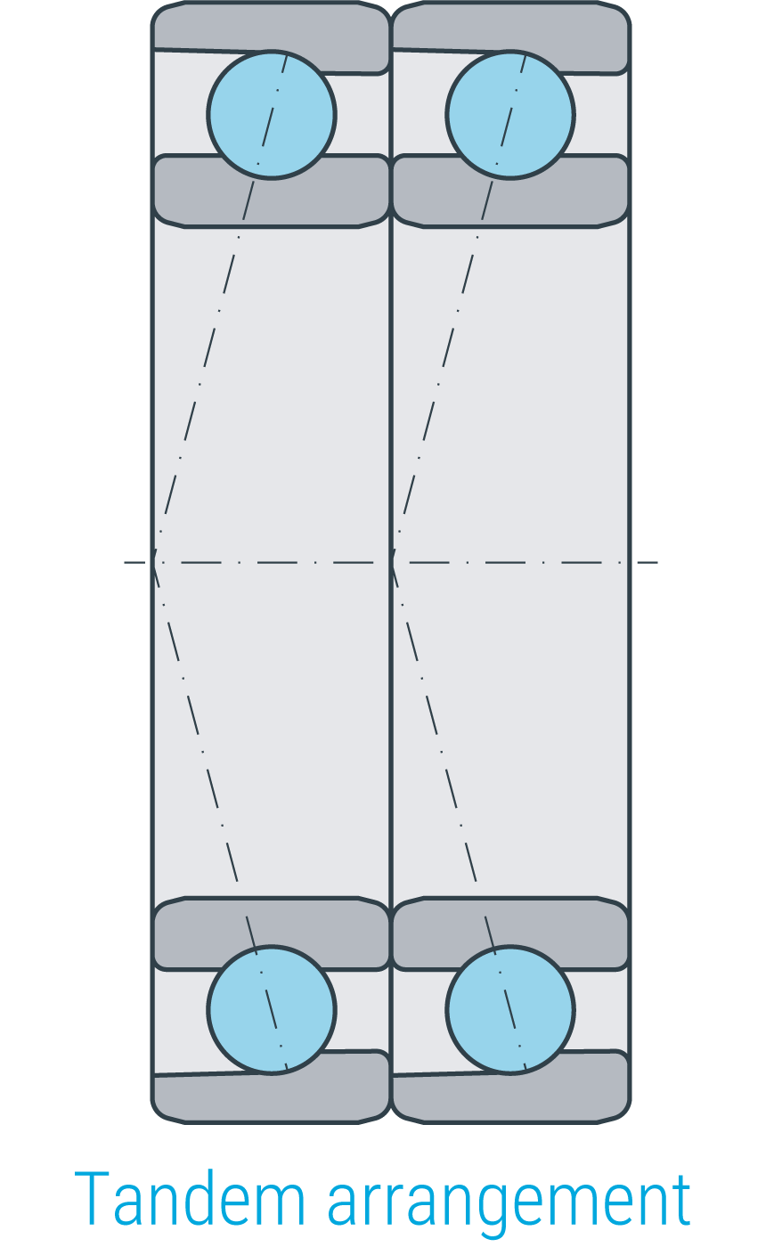
Tandem arrangements, composed of two or three bearings, are used to carry high axial loads in one direction. Thus, high rigidity of the shaft mounting is reached. In tandem arrangements, each bearing carries an equal share of the axial load.
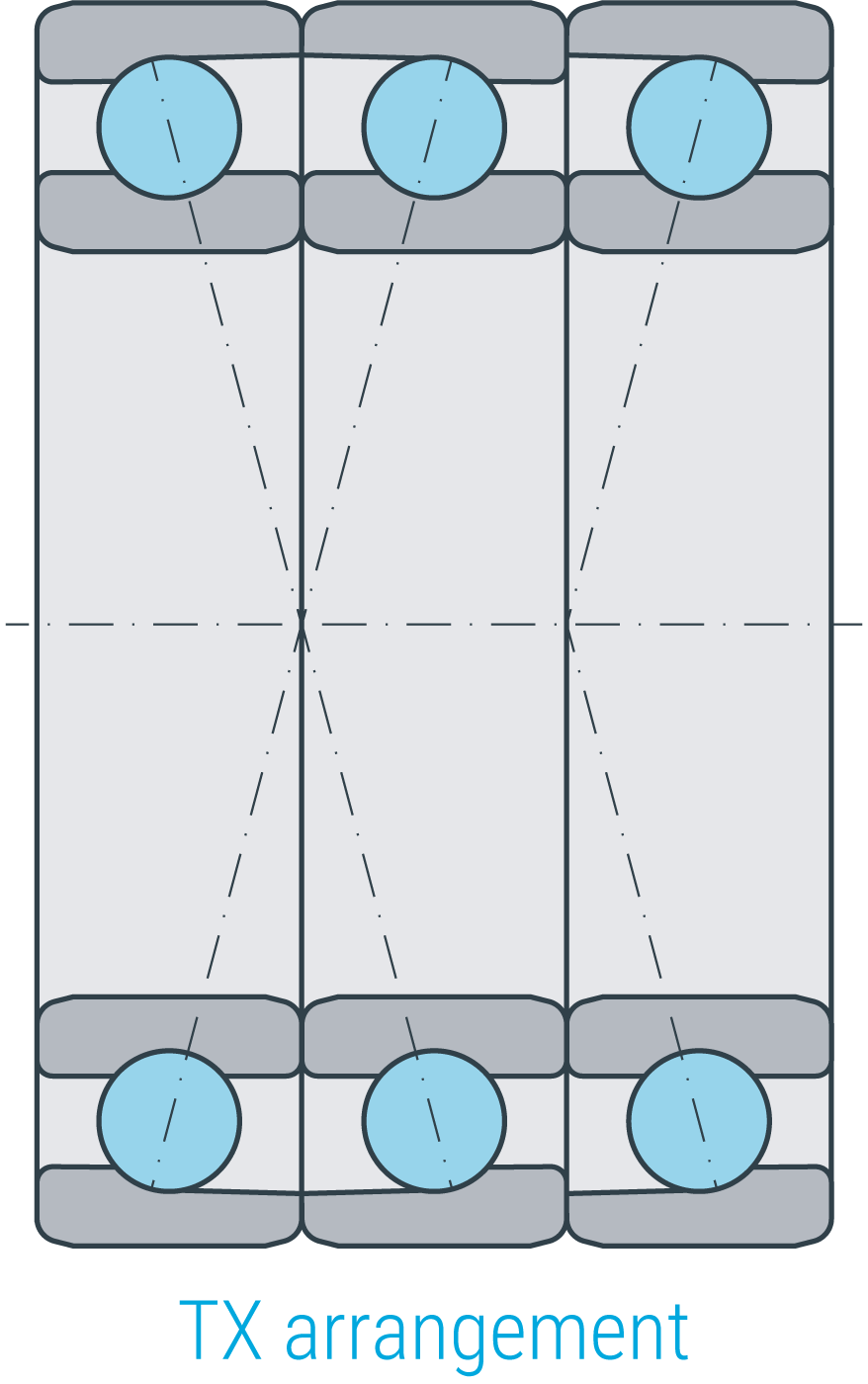
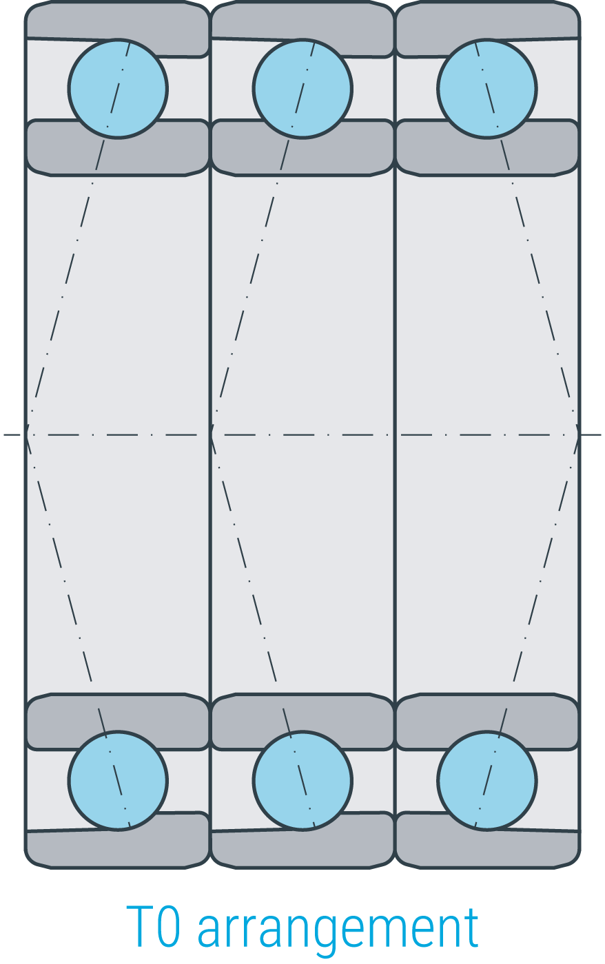
The TO and TX arrangements are, like the tandem arrangement, applied to carry high axial loads in one direction. The additional third bearing is used as a counterstay and makes the multiple arrangement a fixed bearing.
Tolerances for the outer and inner spacer
| Tolerance class | P0, P6, P5, P4 | P2 |
| Difference in width between inner and outer spacer | 3 | 2 |
| Variation of width | 2.5 | 1.3 |
| Axial runout | 2.5 | 1.3 |
(maximum permissible values in µm)
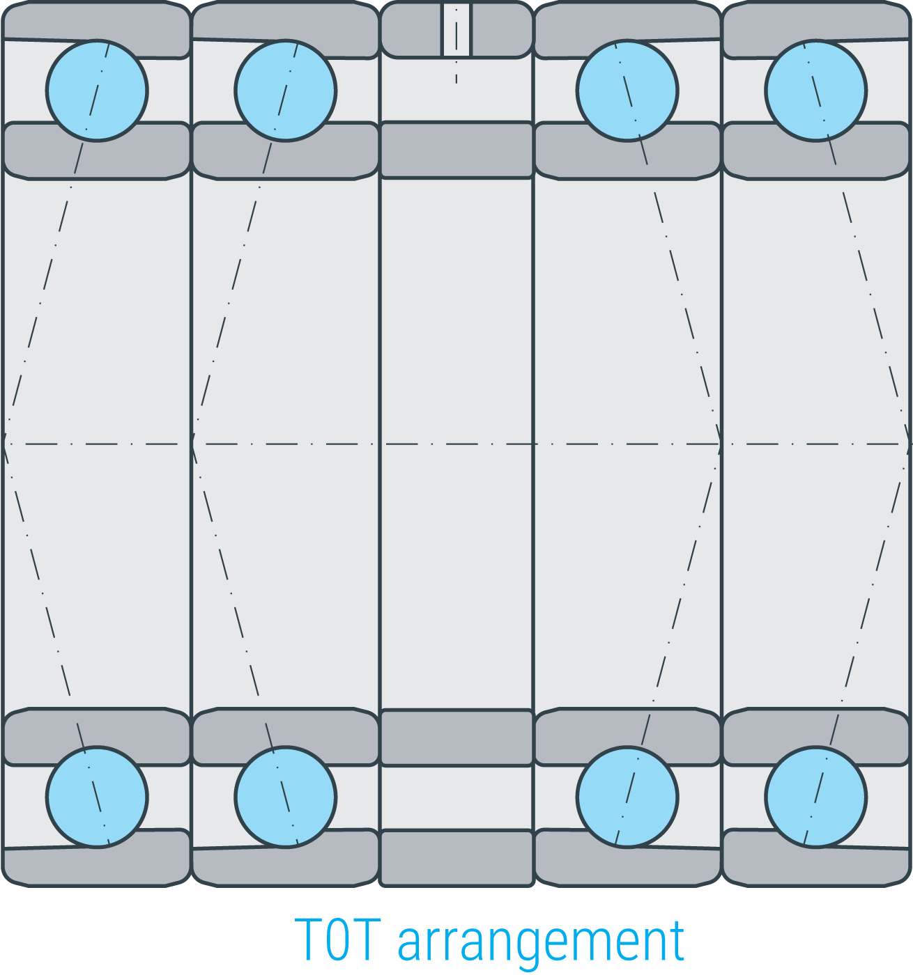
The TOT arrangement is employed for high radial loads and at high axial loads in both directions as a fixed bearing. With this arrangement, very high stiffness is achieved. It is reasonable to install a maximum of three bearings side by side; otherwise, dissipation of heat and lubricant supply to all bearings would become worse or more difficult. To avoid this, spacers should be used here. It is possible to feed the lubricant easily through radial holes in the outer spacer. All arrangements can be delivered as a set upon request.
Clearance
Axial clearance and preload
Axial clearance or zero-backlash do not apply to mounted/ installed and unloaded bearing pairs. In tight fits, axial clearance is diminished or preload of the bearing pair is increased.
Tolerances of the axial clearance
for not-yet installed bearing pairs with universal design in case of X and O arrangement.
Cage
In single row angular contact ball bearings, the cage made of fiberglass-reinforced polyamide 66 is standard in the hole diameter range up to approx. 130 mm. For the use of the cage made of fiberglass-reinforced polyamide 66, the operating temperate is limited to 120 °C, and the same limitations as for the deep groove ball bearings are applicable. Cages made of brass (standard, if not using the cage made of fiberglass-reinforced polyamide 66), steel sheet or brass sheet can be delivered upon request.
Working temperature
SLF-angular contact ball bearings up to 240 mm outer diameter are standard stabilized in dimensions by S0, meaning that they are heat treated to make them usable up to a working temperature of 150 °C. At greater than 240 mm outer diameter, the angular contact ball bearings are standard stabilized in dimensions by S1, meaning that they are heat treated to make them usable up to a working temperature of 200 °C. However, as a rule, the maximum operating temperature is not limited by the dimensional stability of the bearing rings and balls. In many cases, it is limited by cage, seals or lubricant. Please find the relevant information in the corresponding chapters. If you feel uncertain or have specific questions regarding the temperature limits of our bearings, the SLF team is ready to support you.
Greasing/lubrication & sealing
Angular contact ball bearings are standard manufactured without seals; consequently, the bearing location has to be sealed around/on the surrounding components. The sealing must ensure that no moisture and contaminants enter the bearing, and that no lubricant is lost. Angular contact ball bearings without seals are delivered ungreased, but must be lubricated with oil or grease. Choose lubricant according to the application.
Angular contact ball bearings with packing disks and shields can be delivered upon request.
Dimensioning
Dynamic equivalent load
| $$P = F_r$$ | for | $$\frac{F_a}{F_r} \leq{1,14}$$ |
| $$P = 0,35 * F_r + 0,57 * F_a$$ | for | $$\frac{F_a}{F_r} > 1,14$$ |
| $$P = F_r + 0,55 * F_a$$ | for | $$\frac{F_a}{F_r} \leq{1,14}$$ |
| $$P = 0,57 * F_r + 0,93 * F_a$$ | for | $$\frac{F_a}{F_r} > 1,14$$ |
| P | dynamic equivalent load [kN] |
| Fr | radial load [kN] |
| Fa | resultant axial load [kN] |
Static equivalent load
| $$P_0 = F_{0r}$$ | für | $$\frac{F_{0a}}{F_{0r}} \leq{1,9}$$ |
| $$P_0 = 0,5 * F_{0r} + 0,26 * F_{0a}$$ | for | $$\frac{F_{0a}}{F_{0r}} > 1,9$$ |
| $$P_0 = F_{0r} + 0,52 * F_{0a}$$ |
| P0 | static equivalent load [kN] |
| F0r | radial static load [kN] |
| F0a | axial static load [kN] |
Static load safety factor
For statically loaded angular contact ball bearings, one must check not only nominal lifetime L (L10h) , but also the static load safety factor S0.
| S0 | static load safety factor [-] |
| C0 | static load rating [kN] |
| P0 | static equivalent load [kN] |
Required minimum load
To avoid slippage between the contact partners, the angular contact ball bearings must be sufficiently loaded. A radial minimum load in the order of magnitude of
has been shown to be necessary.
In most cases, the radial load resulting from the weight of the components run on the bearing and the external forces alone is higher than the required minimal load. If the achieved value remains below the minimum, please contact an SLF application technician.
Reference speed (calculation basis):
The reference speed is calculated according to ISO 15312 and is the speed at which, under defined reference conditions, a bearing operating temperature of +70 °C is achieved. It is not a speed limit for the application of a bearing but provides the basis to compare the speed suitability of different bearing types.