Description
Full complement cylindrical roller bearings are cage-free, meaning that a maximum number of rolling elements can be accommodated. For this reason, full complement bearings can be subjected to particularly high radial loads, while the limiting speed is significantly lower than that of cylindrical roller bearings.
Thanks to shoulders that are appropriately situated at the bearing rings, the bearings also carry axial forces in one direction. For axial counterstay, place a second bearing mirror-inverted to the first.
Single row full complement cylindrical roller bearings are – except for NJG23..VH series – not detachable.
Dimensions/standards
In single row full complement cylindrical roller bearings, the main dimensions are standardized according to ISO 15 (Radial bearings – boundary dimensions), DIN 616 (Roller bearings – boundary dimensions) or DIN 5412-1 (Roller bearings – cylindrical roller bearings – single row).
Tolerances
As the default, we manufacture single-row full complement cylindrical roller bearings at SLF with standard tolerances (PN) according to DIN 620-2 (Roller bearing tolerances – tolerances for radial bearings) and ISO 492 (Radial bearings – dimensions and tolerances). We also deliver the bearings with other tolerances.
Bearing design types
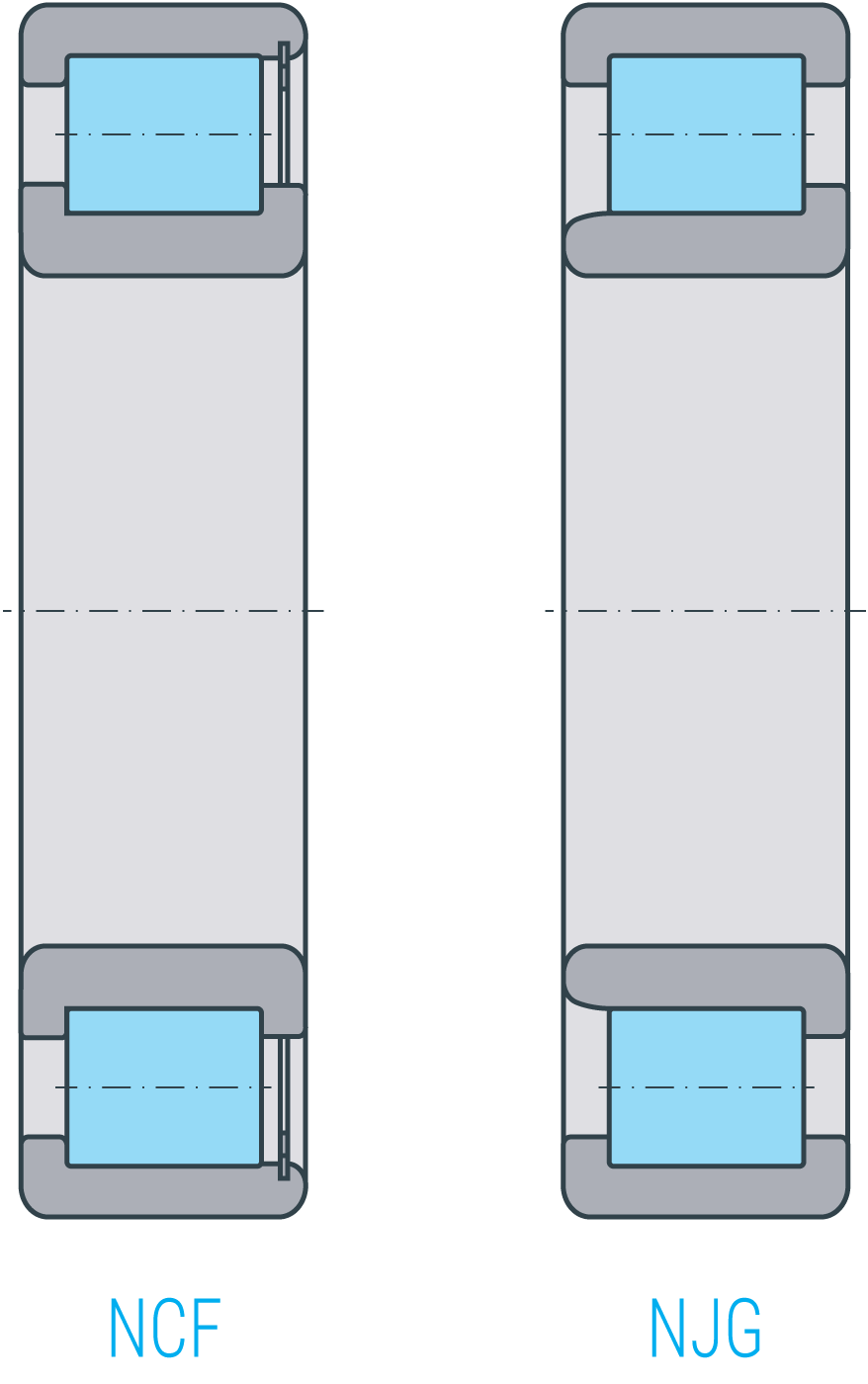
Bearings in the NCF18..V, NCF29..V and NCF30..V series are equipped with two fixed shoulders at the inner ring and one fixed shoulder at the outer ring. At the outer ring’s shoulder-free side, a locking ring prevents the rollers from dropping out. Axial forces are only transmitted in the direction of the fixed outer ring shoulder.
Single-row full-type cylindrical roller bearings are – except in the NJG23..VH series – not detachable. Bearings in the NJG23..VH series carry axial forces in the direction of the inner ring shoulder. In these bearings, the roller cage assembly is non-detachable from the outer ring so that the rolling elements do not drop out even if the inner ring has been taken off.
Clearance
SLF-made cylindrical roller bearings are standard delivered in the clearance class CN according to DIN 620-4 (Roller bearing tolerances – radial clearance) and ISO 5753-1 (Roller bearings – clearance – radial clearance). We can supply design types in other clearance classes or special clearance upon request.
Clearance table for cylindrical roller bearings:
Cage
Full complement cylindrical roller bearings are cageless.
Working temperature
SLF single-row full complement cylindrical roller bearings with a maximum 120 mm outer diameter are standard stabilized in dimensions by S0, meaning that they are subjected to heat treatment that makes them usable up to 150 °C. Above a 120 mm outer diameter, the cylindrical roller bearings are standard stabilized in dimensions by S1, meaning that they are heat treated to make them usable up to a working temperature of 200 °C. However, as a rule, the maximum working temperature is not limited by the dimensional stability of the inner rings and rollers. In many cases, it is limited by the lubricant. Please find the necessary information in the relevant chapters. If you are uncertain or have specific questions regarding our bearings’ temperature limits, don’t hesitate to contact the SLF team.
Greasing/lubrication & sealing
We manufacture single-row full complement cylindrical roller bearings without seals. Consequently, the bearing location must be sealed around/ on the surrounding components. The sealing must ensure that no moisture and/ or contaminants can enter the bearing and that no lubricant is lost.
The cylindrical roller bearings are delivered ungreased but must be lubricated with oil or grease. Choose the lubricant according to the application.
Dimensioning
Dynamic equivalent load
There may exist an axial force Fa in addition to the radial force Fr. The ratio of load must be considered.
\(\)
| $$P = F_r$$ | for | $$\frac{F_a}{F_r} \leq{e}$$ |
| $$P = 0,92 * F_r + Y * F_a$$ | for | $$\frac{F_a}{F_r} > e$$ |
| P | dynamic equivalent load [kN] |
| Fr | radial dynamic load [kN] |
| Fa | axial dynamic load [kN] |
| e, Y | factors [-] |
Factors e and Y for single-row, full complement cylindrical roller bearings
| Series | Mathematic factors | |
|---|---|---|
| e | Y | |
| NCF18 | 0,2 | 0,6 |
| NCF29, NCF30, NJG23 | 0,3 | 0,4 |
Static equivalent load
\(\)$$P_0 = F_{0r}$$
| P0 | Static equivalent load [kN] |
| F0r | maximum radial static load [kN] |
Static load safety factor
For statically loaded cylindrical roller bearings, always inspect static load safety factor S0 in addition to nominal lifetime L (L10h).
\(\)$$S_{0} = \frac{C_0}{P_0}$$
| S0 | static load safety factor [-] |
| C0 | static load rating [kN] |
| P0 | static equivalent load [kN] |
Required minimum load
To avoid slippage between elements in contact, the cylindrical roller bearings must be sufficiently loaded. A minimal radial load in the order of the magnitude of
\(\)$$P > \frac{C_0}{60}$$
has been shown to be necessary.
In most cases, the radial load resulting from the weight of the components run on bearings combined with the external forces is higher alone than the minimal load required. Should this value not be met, contact an SLF application technician.