Spindle bearings
Description
Spindle bearings are a special type of single row angular contact ball bearings. They are often used in the manufacturing of machine tools, as well as in ranges of application with high to extremely high demands in terms of accuracy or permissible speed required by the mounting/ bearing installation.
In comparison with standard angular contact ball bearings, spindle bearings are distinguished by the contact angle, the tolerance classes, and the cage design. Spindle bearings can be delivered with a contact angle of 15° or 25°.
Spindle bearing BS series
The BS719 and BS70 series use a larger number of smaller diameter balls than the B719 and B70 series with identical external dimensions. As a result, higher speeds can be achieved compared to the standard series. The BS series represents a high-performance bearing concept for demanding spindle units that is economical for the customer.
In their main dimensions, high-speed spindle bearings are identical to spindle bearings in the B series. They are particularly characterized by their suitability for higher speeds, as well as by lower friction and heat build-up, and are manufactured in the HS719 and HS70 series.
Dimensions/standards
In spindle bearings, the main dimensions are standardized according to DIN 628-6 (Radial-angular contact ball bearings, single row, contact angle 15° and 25°), ISO 15 (Radial bearings – boundary dimensions) or DIN 616 (Roller bearings – boundary dimensions).
Tolerances
SLF normally produces spindle bearings in P4S according to DIN 620-2 (Roller bearing tolerances – tolerances for radial bearings) and ISO 492 (Radial bearings – dimensions and tolerances).
For P4S, the main directions are defined according to ISO tolerance class 4, while all form and sliding tolerances are set according to ISO tolerance class 2.
Spindle bearings with limited diameter tolerance can be delivered in P4S.K5 upon request.
Bearing design types
Spindle bearings are produced in the B719, B70, B72 and A73 series. They can also be manufactured in various material combinations and designs.
To make it possible to assemble the cage and lubricate the bearing optimally during operation, at least one ring has a stepped shoulder diameter. The bearings are not dismountable.
SLF produces spindle bearings using vacuum- degassed 100Cr6 chromium steel or an equivalent material. For special applications, SLF produces the spindle bearings with ceramic balls and roller bearing rings made of Cronidur® 30.
SLF normally manufactures the spindle bearings in the universally used UL, UM and US designs, which can be mounted in any arrangement. But we can also deliver matched bearing sets with defined preload of the bearing.
Bearing arrangements
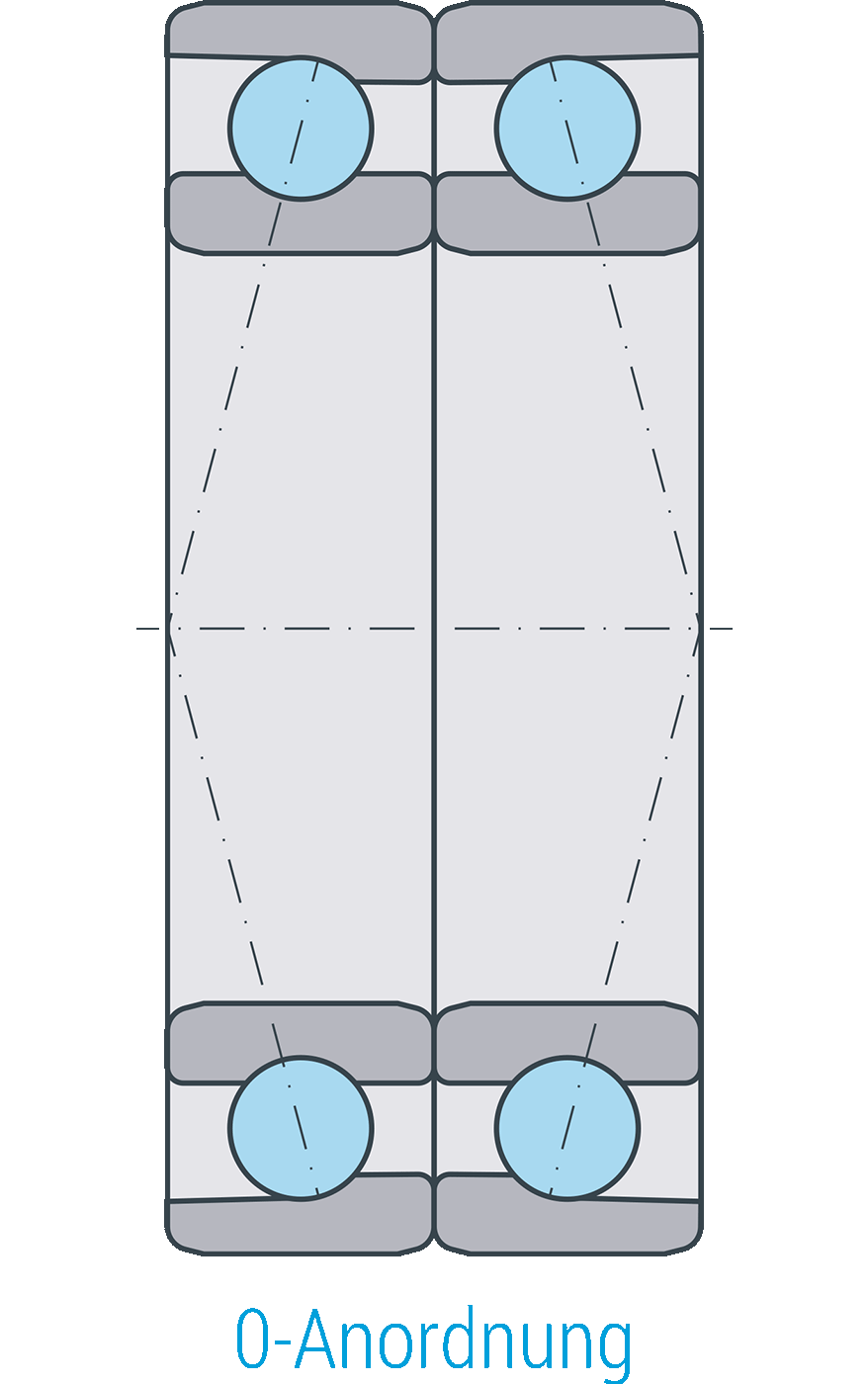
O-arrangement (designation suffix DB)
The thrust lines diverge in the bearing axis direction. This results in a large support width H on the bearing axis. This arrangement provides a very stiff mounting that withstands the tilt moment, and the mounting carries axial forces in two directions.

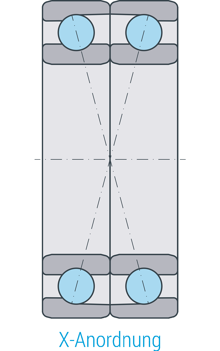
X arrangement (designation suffix DF)
The thrust lines converge in the bearing axis direction. This results in a short support width H on the bearing axis. Tilting stiffness is lower than in the O arrangement. The arrangement better withstands alignment errors. Load-suspension and bearing spring resistance are analogous to the O arrangement.
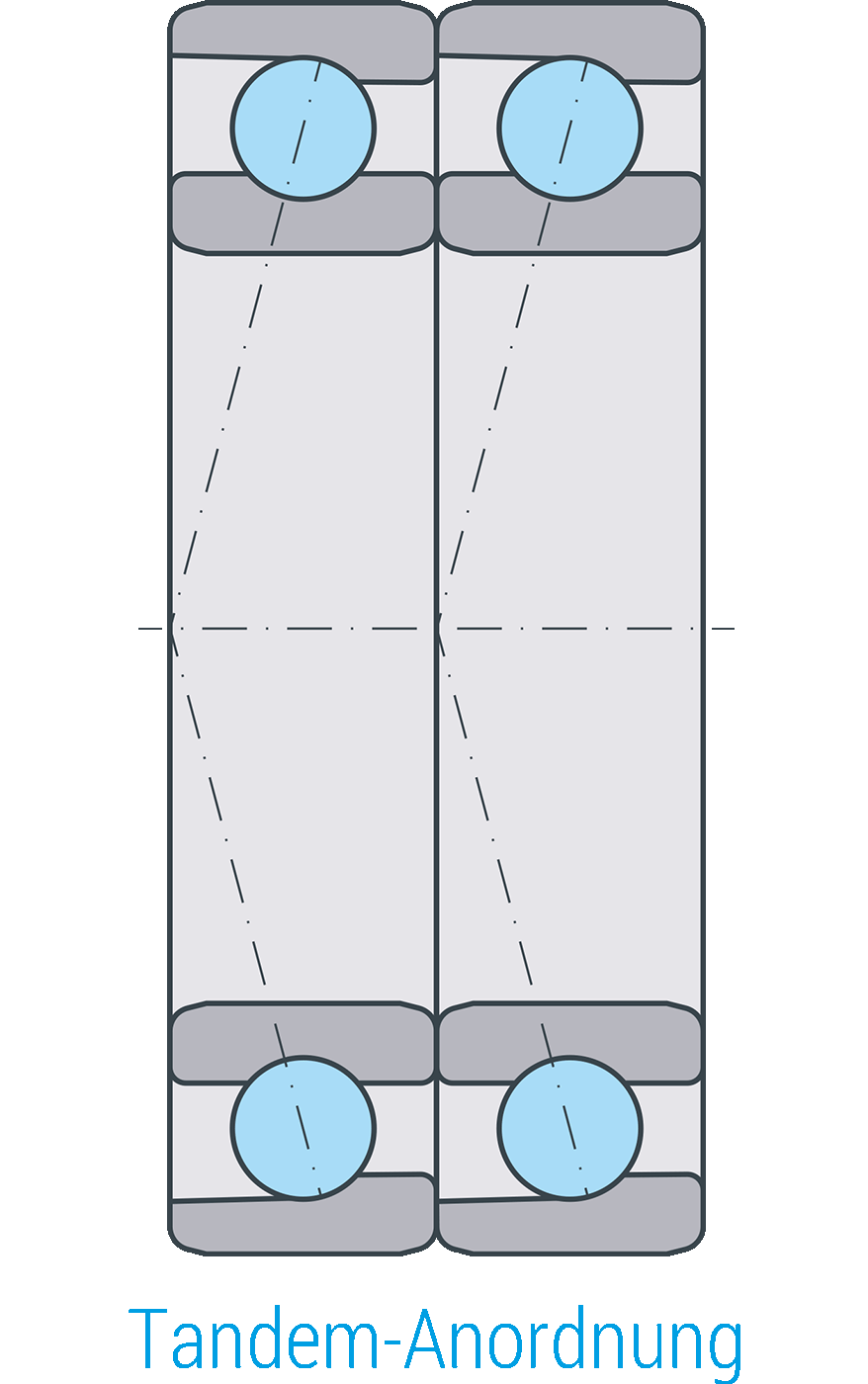
Tandem arrangement (designation suffix DT)
Both paired bearings are arranged in parallel in the load direction. As a result of this arrangement, in the load direction, a higher axial load is possible than with a single bearing. Each of the two bearings carries the same amount of the axial load. However, it must be noted that the tandem pair must be set against a third bearing in each case.
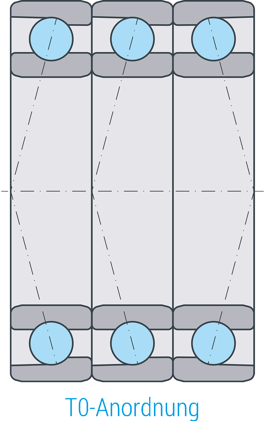
Multiple bearing arrangements
At higher loads or if high stiffness values are required, then 3, 4, and sometimes even 5 bearings are put together into sets and installed. At SLF, bearings of this pairing type are manufactured, marked, and packed in pairs or sets.
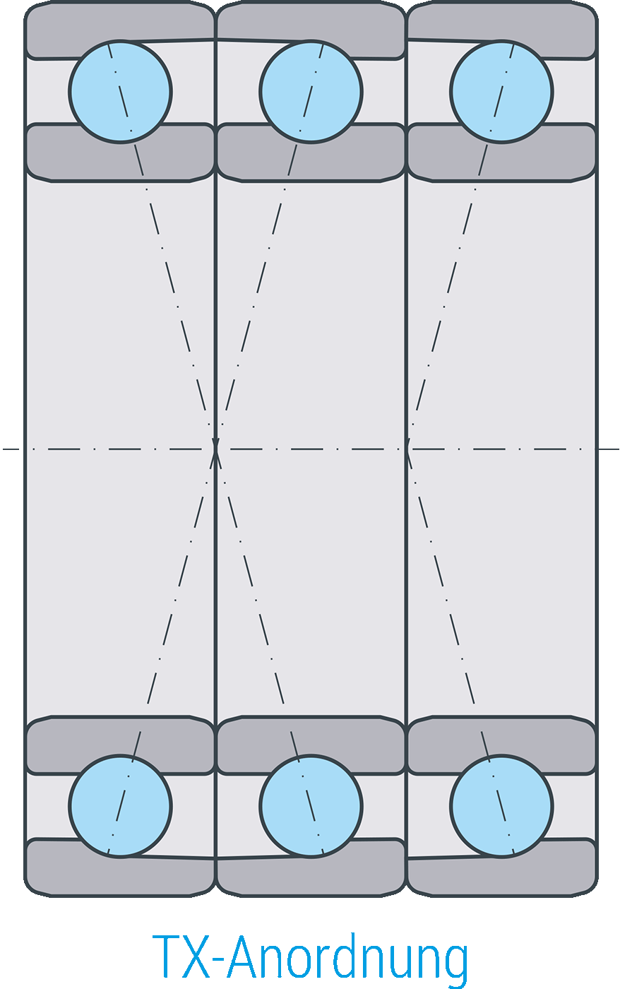
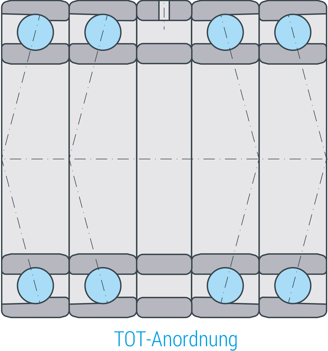
Distance washers
For spindle bearings in universal design, distance washers may be used in all arrangements. When installing distance washers between the paired bearings, it is possible to, for instance, increase support width H, enhance lubrication, reduce or eliminate frictional heat, and vary the preload. Information about the difference sizes required is available upon request. When manufacturing the distance washers, ensure that the outer and inner ring have exactly the same width and are plane-parallel.
Tolerances for the outer and inner distance washers
| Tolerance class | P4 | P4S, P2 |
| Difference in width between inner and outer distance washer | 3 | 2 |
| Variation of width | 2.5 | 1.3 |
| Axial runout | 2.5 | 1.3 |
maximally permissible values in µm
Hybrid spindle bearings
Hybrid spindle bearings are bearings whose raceways are made of antifriction bearing steel, and whose balls are made of a ceramic material (silicon nitride Si3N4) with the highest homogeneity and hardness. At the same time, ceramic balls weigh less than steel bearings. These characteristics result in lower centrifugal forces and less friction. They are electrically insulating and are non-magnetic. Moreover, they withstand corrosion. These bearings are specifically engineered to serve as high-performance bearings for machine tool spindles and provide the prerequisites for top performance.
Originally, hybrid bearings were primarily used in the high-speed range. However, thanks to their lifetime being the same or longer than that of steel bearings, they are also in use in all other bearing design series.
Due to the outstanding properties of ceramic, hybrid bearings are characterized by significantly reduced friction during operation, and consequently have the following advantages over steel balls:
- withstand about 20% higher speeds
- better emergency run properties in case of poor lubrication
- higher bearing stiffness
- lower vibrations
- less noise level
- better adapted acceleration and deceleration characteristics
Preload
The predefined axial forces are: low (L), medium (M) and high (S).
The preloads specified in the bearing tables are applied to the axial preload of bearing pairs (in O or X arrangement). When combining more than 2 bearings, multiply the preloads as given below:
| Pair (Matching) | Factor |
| DB, DF | 1 |
| TBT, TFT | 1.35 |
| QBT, QFT | 1.6 |
| QBC, QFC | 2.0 |
Cage
SLF normally equips spindle bearings with a one-piece, outer shoulder-guided solid window cage made of laminated fabric (a cotton fabric saturated with phenolic resin). The cages made of this high-performance material withstand high centrifugal and acceleration forces, as well as working temperatures up to 100 °C. This material has excellent tribologic characteristics; when lubricant is insufficient, it is characterized by outstanding emergency running properties.
For working temperatures above (>) 100 °C, we recommend the use of brass cages or PEEK cages. The maximal working temperature of PEEK cages is 150 °C.
Working temperature
SLF spindle bearings with an outer diameter up to 240 mm are standard stabilized in dimensions by S0, meaning that they are heat treated to make them usable up to a working temperature of 150 °C. At greater than 240 mm outer diameter, the deep groove ball bearings are standard stabilized in dimensions with S1, meaning that they are heat treated to make them usable up to a working temperature of 200 °C. However, the maximal operating temperature is not limited by the dimensional stability of the bearing rings and balls. In many cases, it is limited by the cage, the seals, or the lubricant.
| Component | Upper range of use in terms of temperature (Upper working temperatures) |
| Roller bearing rings | 150°C |
| Laminated fabric cage (standard) | 100°C |
| Brass cage | 150°C |
| PEEK cage | ca. 260°C (150°C without limitation in performance) |
| Packing disks made of NBR (2RSD) | 110°C |
| Lubricant grease L252 (standard) | 120°C |
If you are uncertain or have specific questions regarding the temperature limits of our bearings, the SLF team is ready to support you.
Greasing/lubrication & sealing
Spindle bearings with sealed design (2RSD) are – as specified in the bearing tables – part of the SLF manufacturing program. Greasing/ lubrication of these maintenance-free bearings will allow the bearings to run at the highest speeds at low temperatures over a long period of time.
The low outlay necessary for assembly, lubrication, and maintenance offers an optimal solution for a long period of service for the user.
Unsealed ungreased spindle bearings must be lubricated with oil or grease by the user. Here, the bearing position must be sealed around / on the surrounding components.
Bearings of the same size and series in unsealed designs are interchangeable with the same bearings in sealed designs.
Dimensioning
Spindle bearings must guide machine parts very precisely and simultaneously transfer forces even at very high speeds in a reliable manner. The bearings are primarily chosen according to precision, stiffness, and running characteristics. In many applications, the bearings must be fatigue endurable.
To check the fatigue limit, the load ratio S0* is calculated by means of the equation below:
| S0* | Load ratio for fatigue limit (dynamic load safety factor) | [-] |
| C0 | Static load rating | [N] |
| P0* | Equivalent load P0* is calculated by means of the forces of the dynamic load according to the equation of the static equivalent load. | [-] |
The minimal value for the load ratio S0* depends on the bearing design type and the component material.
To provide sufficient fatigue strength, the load ratio S0* should achieve the following values from the table:
| Bearing design type | Contact angle 15° | Contact angle 20° | Contact angle 25° | |||
| $$\frac{F_{0a}}{F_{0r}} \leq 1.09$$ | $$\frac{F_{0a}}{F_{0r}} > 1.09$$ | $$\frac{F_{0a}}{F_{0r}} \leq 1.20$$ | $$\frac{F_{0a}}{F_{0r}} > 1.20$$ | $$\frac{F_{0a}}{F_{0r}} \leq 1.30$$ | $$\frac{F_{0a}}{F_{0r}} > 1.30$$ | |
|---|---|---|---|---|---|---|
| B / HCB | 8 | 12 | - | - | 8 | 10 |
| HS / HC | 8 | 12 | - | - | 8 | 10 |
| BS / HCBS | - | - | 8 | 11 | - | - |
| XC | 3 | 4 | - | - | 3 | 4 |
Static equivalent load
Static equivalent bearing load P0 is calculated from the loads affecting the bearing in the axial and radial directions, according to the formula below.
| $$P_0 = F_{0r}$$ | for | $$\frac{F_{0a}}{F_{0r}} \leq e$$ |
| $$P_0 = 0.5 * F_{0r} + Y * F_{0a}$$ | for | $$\frac{F_{0a}}{F_{0r}} > e$$ |
| Contact angle | e | Y |
| 15° | 1,09 | 0,46 |
| 20° | 1,20 | 0,42 |
| 25° | 1,30 | 0.38 |
| P0 | static equivalent load [kN] |
| F0r | radial static load [kN] |
| F0a | axial static load [kN] |
| e, Y | factor [-] |
Static load safety factor
To use the high accuracy of spindle bearings, the static load safety factor S0 must be >2.
| S0 | static load safety factor [-] |
| C0 | static load rating [kN] |
| P0 | static equivalent load [kN] |
Speed limits in bearing arrangements
The speed limits listed in the product table are reduced in the case of rigidly or more highly preloaded bearings, as well as for bearing pairs or groups. The specified speed must be multiplied by the reduction factor fr.
| $$Factor f_r$$ | ||||
|---|---|---|---|---|
| bearing preload | ||||
| low | medium | high | ||
| L | M | S | ||
| inter-bearing distance large | ||||
| 0,85 | 0,75 | 0,5 | ||
| 0,8 | 0,7 | 0,5 | ||
| 0,75 | 0,65 | 0,45 | ||
| Fixed bearing | Floating bearing | |||
| 0,75 | 0,6 | 0,35 | ||
| 0,65 | 0,5 | 0,3 | ||
| 0,65 | 0,5 | 0,3 | ||
| 0,72 | 0,57 | 0,37 | ||
| 0,54 | 0,4 | 0,37 | ||